| |
Fastening Technique |
| Pipe clamps for Nagory PPR- pipes have to correspond to the external diameter of the plastic pipe
Furthermore it is important, that the fastening material does not damage the surface of the pipe mechanically. The selection of the fastening material and its application has to be determined as a fixed point or sliding point. |
| |
|
| |
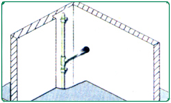
Fixed Points |
| |
On locating fixed points the pipelines are divided into individual sections. This avoids uncontrolled movements of the pipe. In principle, fixed points have to be measured and installed in a way, that the forces of expansion of Nagory PPR-pipes as well as probable additional loads are accommodated.
On using threaded rods of threaded screws, the drop from the ceiling should be as short as possible. Swinging clamps should not be used as fixed points. It is always possible to install vertical distributions rigidly. Risers do not require expansion loops, provided that fixed points are located immediately before and after a branch. To compensate the forces arising from the linear expansion of the pipe there must be sufficient and stable clamps and mountings. |
| |
|
| |
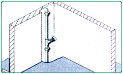
Sliding points |
| |
Sliding clamps have to allow axial movements of the pipe without damaging the pipe.
On locating a sliding clamp it has to be ensured that movements of the pipelines are not hindered by fittings installed next to the clamps.
The special characteristics of Nagory PPR - pipe clamps makes them suitable for noise insulation and, when installed in accordance with the below instructions. |
| |
|
| |
Installation Advice |
| |
The application of distance rings depends on the type of pipe. |
| |
| Fastening |
Nagory PPR -pipe |
| Sliding Point |
1 distance ring |
| Fixed Point |
no distance ring |
|
| |
|
| |
Linear Expansion |
| |
The linear, expansion of pipes depends on the difference of operating temperature to installation temperature: |
| |
T = τoperating temperature - τinstallation temperature
Therefore cold water pipes have practically no linear expansion.
Because of the heat dependent expansion of the material, the linear expansion must be specially considered in case of warm water and heating installations. The requires a distinction of the types of installation, i.e. |
| |
- Concealed installation
- Installation in ducts
- Open Installation
|
| |
|
| |
Concealed Installation |
| |
Concealed installations generally do not require a consideration of the expansion pipes.
The insulation according to DIN 1988 or the EnEv (energieensparverordnung ) gives enough expansion space for the pipe. In the case where the expansion is greater than the room to move in the insulation, the material absorbs any stress arising from a residual expansion.
The same applies to pipes, which do not have to be insulated according to current regulations.
A temperature induced linear expansion is prevented by the embedding in the floor, concrete or plaster. The compressive strain and tensile stress arising from this are not critical as they are absorbed by the material itself. |
| |
|
| |
 |
| All pipe clamps in the ducts have to be installed as fixed points |
| |
 |
| Favourable fixing |
| |
 |
| Large diameter pipe liner |
| |
 |
| Installation of a spring leg |
| |
|
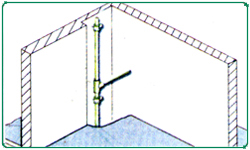
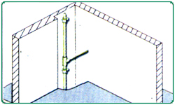
Installation in Ducts |
The installation of risers of Nagory PPR pipe requires a branch pipe, which is elastic enough to take the linear expansion of the riser.
- This can be ensured by a favorable fixing of the riser in the duct.
- An adequate large pipe linear also gives sufficient elasticity to the branch-off pipe.
- Furthermore the installation of a spring leg gives the appropriate elasticity.
|
Open Installation |
In case of open installed pipes, as presentation is important there should be no deformation of the pipe work.. The coefficient of linear expansion of Nagory PPR pipes: α Nagory PPR = 0.150mm/mK
Therefore it is recommended to plan and install visible Nagory PPR pipes. Where linear expansion has to be considered. The following formula, calculation examples, data-tables and diagrams help to determine the linear expansion. Essential for the calculation of linear expansion is the difference between working temperature and maximum installation temperature. |
| |
| Calculation of Linear Expansion (calculation example) |
Symbol |
Meaning |
Value |
Measuring Unit |
Δ |
Linear expansion |
? |
mm |
α |
Linear expansion coefficient |
0.15 |
mm/mk |
L |
Pipe length |
25.0 |
m |
TW |
Working temperature |
60.0 |
°C |
TM |
Installation temperature |
20.0 |
°C |
ΔT |
Temperature difference
between working and
installation temperature
(Δ = Tw-TM) |
40.0 |
K |
| The linear expansion Δ is calculated according to the following formula : |
| Δ = α×L×ΔT = 0.15mm/mk×25.0m×40K =150.0mm |
|
| |
Installation Principles |
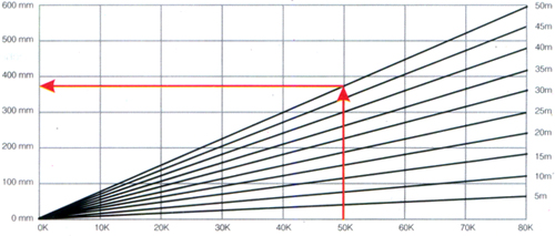
| The linear expansion. described above, can be taken from the following tables and diagrams. |
| |
|
|
| |
| Linear expansion ΔL in (mm): Nagory PPR pipe α=0.150mm/mK |
| |
Diference in temperature ΔT=Toperating temperature-Tinstallation temperature |
Pipe length |
10K |
20K |
30K |
40K |
50K |
60K |
70K |
80K |
|
Linear expansion Δ L (mm) |
5mm |
8 |
15 |
23 |
30 |
38 |
45 |
53 |
60 |
10m |
15 |
30 |
45 |
60 |
75 |
90 |
105 |
120 |
15m |
23 |
45 |
68 |
90 |
113 |
135 |
158 |
180 |
20m |
30 |
60 |
90 |
120 |
150 |
180 |
210 |
240 |
25m |
38 |
75 |
113 |
150 |
188 |
225 |
263 |
300 |
30m |
45 |
90 |
135 |
180 |
225 |
270 |
315 |
360 |
35m |
53 |
105 |
158 |
210 |
263 |
315 |
368 |
420 |
40m |
60 |
120 |
180 |
240 |
300 |
360 |
420 |
480 |
45m |
68 |
135 |
203 |
270 |
338 |
405 |
473 |
540 |
50m |
75 |
150 |
225 |
300 |
375 |
450 |
525 |
600 |
|
| |
|
| |
Nagory PPR Pipe |
| |
|
| |
Difference in temperature ΔT (K) |
| |
Linear expansion due to temperature difference between operating temperature and installation temperature can be compensated by different installation techniques. |
| |
|
| |
|
|
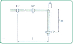
Bending Side |
| In most cases direction changes can be used to compensate for linear expansion in pipes. The length of a bending side LBS is calculated acc. to the following formula in consideration of the calculated linear expansion and pipe dimension. |
 |
| The values of the bending side can be taken directly from the tables and diagrams. |
Symbol |
Meaning |
LBS |
Length of the bending side |
(mm) |
K |
Material specify constant |
15.0 |
d |
Outside diameter |
(mm) |
Δ |
Linear expansion |
(mm) |
L |
Pipe Length |
(m) |
FP |
Fixed point |
|
SP |
Sliding point |
|
|
| The bending side length is calculated according to the following formula LBS= K×√d×Δ |
| |
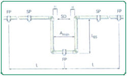
Expansion Loop |
In most cases direction changes can be compensated through the change in direction, It becomes necessary to install an expansion loop with long and straight pipelines.
Consider the length of the bending side LBs as well as the breadth of the pipe bend Amin on constructing an expansion loop. |
Symbol |
Meaning |
Amin |
Width of the expansion loop |
(mm) |
SD |
Safety distance |
150mm |
|
This pipe bend Amin is calculated acc. to the following formula:
Amin= 2×AI+SD
The width of the expansion loop Amin should be at lease 210mm |
| |
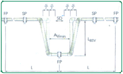
Pre-stress |
Where space is limited, it is possible to shorten the total width Amin as well as the length of the bending side IBSV by its pre-stressing.
Pre-stress installation, If the planned and carried out carefully. Offer an optically perfect installation, as the linear expansion is hardly visible.
The side length LSV is calculated acc. to the following calculation example: |
Symbol |
Meaning |
Value |
Measuring unit |
LBSV |
Length of pre-strees |
- |
mm |
|
The side length of expansion loops with pre-stress is calculated acc. to the following example:
LBSV= K×√d×Δ/2 |
| |
|
|
| |
Support Intervals |
| |
Nagory PPR -pipe SDR 6 & SDR 7.4
Table to determine support intervals in conjunction with temperature and outside diameter |
| |
Difference
in temp.
ΔT[K] |
Pipe diameter d [mm] |
16 |
20 |
25 |
32 |
40 |
50 |
63 |
75 |
90 |
110 |
| Support intervals in cm |
0 |
70 |
85 |
105 |
125 |
140 |
165 |
190 |
205 |
220 |
250 |
20 |
50 |
60 |
75 |
90 |
100 |
120 |
140 |
150 |
160 |
180 |
30 |
50 |
60 |
75 |
90 |
100 |
120 |
140 |
150 |
160 |
180 |
40 |
50 |
60 |
70 |
80 |
90 |
110 |
130 |
140 |
150 |
170 |
50 |
50 |
60 |
70 |
80 |
90 |
110 |
130 |
140 |
150 |
170 |
60 |
50 |
55 |
65 |
75 |
85 |
100 |
115 |
125 |
140 |
160 |
70 |
50 |
50 |
60 |
75 |
80 |
95 |
105 |
115 |
125 |
140 |
|
| |
|
| |
Support Intervals |
| |
Nagory PPR -pipe SDR 11
Table to determine support intervals for cold water application (temperature of medium: 20° C) in conjunction with outside diameter. |
| |
Pipe diameter d[mm] |
20 |
25 |
32 |
40 |
50 |
63 |
75 |
90 |
110 |
125 |
160 |
Support intervals in cm |
60 |
75 |
90 |
100 |
120 |
140 |
150 |
160 |
180 |
200 |
225 |
|
| |
|
| |
Thermal insulation of warm water pipes |
| |
The decree for energy saving thermal protection and energy saving technique for buildings
Extract from § 12 addendum 5 of the EnEv |
| |
| Line |
Type of pipe/fitting |
Minimum thickness of insulation referred to thermal conductivity of 0.035 W/(mK) |
1 |
Inner diameter upto 22mm |
20mm |
2 |
Inner diameter more than 22 mm up to 35 mm |
30mm |
3 |
Inner diameter more than 35 mm up to 100 mm |
same as inner
diameter |
4 |
Inner diameter more than 100 mm |
100mm |
5 |
Pipes and fittings, in wall- and ceiling openings, in crossing area
of pipes, at pipe connections, at distributors |
1/2 of the demand
of line 1 to 4 |
6 |
Pipes of central heating which have been installed after
introduction of this decree between heated rooms of various
users |
1/2 of the demand
of line 1 to 4 |
7 |
Pipes in floor construction |
6mm |
|
| |
|
| |
Central heating pipes, installed in heated rooms or building parts between heated rooms of the one user, where heat output can be controlled by open stop valves do not require a minimum thickness of the insulation.
This even applies to warm water pipes up to an inner diameter of 22 mm in flats, which are neither in the circulation nor have an additional electric heating.
Applying material with thermal conductivity different to 0.035 W/m. K the minimum thickness of the insulation has to be converted correspondingly.
For the conversion and the thermal conductivity of the insulation the ways ad values of calculation described in the technical regulations must be applied.
The minimum insulation according to the table for heating distributions and heating pipes can be reduced as far as the same limit of heat output even for further insulation demands in consideration of the insulating effect of the pipe walls are guaranteed.
According to this decree Nagory PPR - pipes and fittings have to be insulated against loss of heat. The insulation thickness depends on the respective installation.
The heat conductivity figure of Nagory PPR PP-R is 0.15 W/(Mk)
This means that in terms of heat transfer Nagory PPR pipes and fittings offer a significantly higher degree of self-insulation compared to metal pipes. |
| |
|
| |
Insulation thickness according to Decree for Energy Saving for Nagory PPR-pipes |
| |
Due to the high insulation values of the Nagory PPR PPR-C material the level of insulation thickness compared to metallic pipe systems can be reduced according to the following minimum insulation thickness. |
| |
Thermal
Conductivity
Dimensions |
0.030 W/(mK) |
0.035 W/(mK) |
0.040 W/(mK) |
Minimum insulation thickness in mm |
|
50% |
100% |
50% |
100% |
50% |
100% |
16mm |
6.1 |
12.8 |
8.0 |
17.0 |
10.1 |
22.2 |
20mm |
6.1 |
12.9 |
7.8 |
16.8 |
9.7 |
21.6 |
25mm |
6.0 |
13.0 |
7.6 |
16.7 |
9.3 |
21.0 |
32mm |
9.4 |
19.9 |
11.8 |
25.5 |
14.4 |
32.2 |
40mm |
9.3 |
19.8 |
11.5 |
25.1 |
13.9 |
31.2 |
50mm |
9.0 |
19.7 |
11.0 |
24.7 |
13.2 |
30.2 |
63mm |
13.1 |
27.9 |
15.9 |
35.0 |
19.0 |
42.9 |
75mm |
15.6 |
33.4 |
19.0 |
41.7 |
22.6 |
51.1 |
90mm |
18.8 |
40.2 |
22.8 |
50.1 |
27.1 |
61.3 |
110mm |
23.1 |
49.1 |
27.9 |
61.1 |
33.1 |
74.7 |
|
| |
|
| |
Thermal Insulation Cold Water Pipes |
| |
As stipulated in DIN 1988, part 2
Potable water plants have to be protected against heat gain and the formation of condensation.
Standard values for the minimum insulation thickness have to be taken from the following table.
The given insulation thickness are applicable to all pipe materials and also to Nagory PPR-pipes.
The above values are corresponding to the German industry standard (DIN) and have to be adapted to the respective national regulations.
Standard values for the minimum insulation thickness for the insulation of potable water plants (cold) Insulation thickness |
| |
| Type of the installation |
Insulation thickness at
A = 0.040 (W/mK)* |
Open installed pipe in a not heated room
(i.e. basement) |
4 mm |
| Open installed pipe, in a heated room |
9 mm |
| Pipe in a duct, without hot water pipes |
4 mm |
| Pipe in a duct, based hot water pipes |
13 mm |
| Pipe in a pipe chase riser |
4 mm |
| Pipe in a pipe chase, basede hot water pipes |
13 mm |
| Pipe on a concrete floor |
4 mm |
|
| |
*the insulation thicknesses, applied t6 d diameter of d = 20 mm, for other coefficients of thermal conduction have to be calculated correspondingly. |
| |
|
| |
Pressure Test/Test control |
| |
According to the Technical Rules for potable water Installations DIN 1988
All pipelines have to be (while still visible) hydraulically pressure tested. The test pressure has to be
1.5 times of the operating pressure.
When carrying out the material properties of Nagory PPR PPR-C pipes lead to an expansion of the pipe. This influences the test result can because by the coefficient of thermal expansion of Nagory PPR PPR-C pipes. Different temperatures of pipe and test medium lead to alterations of pressure. A temperatures change 10 K corresponds to a pressure difference of 0.5 to 1 bar. Therefore the highest possible constant temperature of the test medium has to be ascertained at the hydraulic pressure test of installations with Nagory PPR PPR-C Pipes.
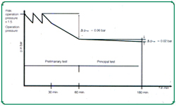
The hydraulic pressure test requires a preliminary, principal and final test.
For the preliminary test, a pressure of 1.5 times of the highest possible operating pressure has to be produced. This test pressure has to be re-established twice within an interval of 10 minutes. After a test time of a further 30 minutes the test pressure must not drop more than 0.6 bar and no leakage should have appeared.
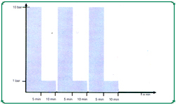
The preliminary test to be followed directly by the principal test. Test time is 2 hours. On doing so the test pressure taken from the preliminary test may not fall more than 0.2 bar. After completion of the preliminary and principal tests the final test must be conducted, which has to be effected with a test pressure of alternate 10 and 1 bar in a rhythm of at least 5 minutes.
Between each test course the pressure has to be removed.
No leakage must appear at any point of the tested installation. |
| |
|
| |
Measuring of the Test Pressure |
| |
Measuring has to be done with a manometer allowing a perfect reading of a pressure change of 0.1 bar. The manometer has to be placed at the deepest point of the Installation. |
| |
|
| |
Test Record |
| |
A record of the hydraulic pressure test has to be prepared and signed by the client and contractor stating place and date. |
| |
|
| |
Pressure Test/ Test Control |
| |
|
| |
|
| |
Flushing of pipes |
| |
The technical rule for potable water installations (TRWI)
Includes a paragraph about flushing of pipes. Which has to be carried out with an air water-mixture under pressure.
Basically all potable water plants, independent of their material, have to be flushed thoroughly after their installation. The following requirements have to be complied with before the installation can be put into service.
- Protection of the potable water quality
- Avoidance of corrosion damage
- Avoidance of malfunctions of armatures and apparatus
- Cleanliness of the inner surface of the pipe
These requirement are met by
- Flushing with water
- Flushing with air-water-mixture
On choosing the type of flushing required, the experiences of the installer, the requirements of the client and the instructions of the system manufacturer have to be observed.
For potable water installations according to DIN 1988, which the Nagory PPR PPR-C pipes system complies with, "1-flushing with water" is sufficient.
The installation of the Nagory PPR PPR-C pipes system requires no additives. i.e.glue, solvent mixtures, etc.; the joining method is fusion. This system is pure material and remains so after the fusion.
For this reason it is sufficient to flush the installation with water according to procedure"1". |
| |
|
| |
Earth Wire |
| |
DIN VDE 0100, Part 701 contains safety measures for rooms containing baths or showers. Among other aspects, this standard regulates the potential balance for such rooms.
The standard stipulates that all conductive such as metal baths and shower trays metal outlet valves, metal stench traps and metal pipe systems (e.g. drinking water and heating pipe systems) must be connected to each other. The connection to an earth conductor must be proviced, at a central point, e.g. in the building's mini-distributors installation(power circuit distributors).
Information on renovating portable dirinking water pipe systems using Nagory PPR -pipes:
Where metal pipes are replaced by Nagory PPR PPR-C pipes, the potential blance can not be created by the water pipes.
Care should be taken to ensure that the potential balance is checked out by a qualified electrician. |
| |
|
| |
Transport and Storage |
| |
Nagory PPR PPR-C pipes may be stored outside at any temperature. A solid base for the pipe is very important, to avoid a deformation of the pipes while in transport and storage. |
| |
|